

HVAC systems can be very elaborate. But with some research, it’s surprisingly easy to learn how to replace a thermostat with a smart, programmable Raspberry Pi thermostat. Even basic, student-focused electronic kits contain all the parts necessary to control the heat in a house.
This smart Raspberry Pi thermostat integrates with Home Assistant, a part of retrofitting a snowy cabin into a smart home.
This post will focus on the Arduino Uno which controls the three zones, as well as the Node RED code which makes it smart.
Replacement Thermostat Design
Every HVAC system is a bit different…
Not just electronically, but because every climate is a bit different. Here in the foothills surrounding Denver, cold is the enemy. But heating a home with propane is expensive. It’s also slow: the radiant heat comes from hot water running through pipes in heaters near the floorboards.

The first thing I noticed when examining the existing three-zone heating system was that the temperature readings were… imprecise. Each of the three old-school Honeywell wall-mounted thermostats had only the most rudimentary, mechanical temperature sensor. They were also placed centrally in the house. However, what we’re most concerned with is the temperature along the walls. This is where the pipes are, which we need to protect from freezing.
Two-Wire Thermostats
Thankfully, the electrical design of the HVAC system was very simple. When I removed the three thermostats, each of the three zones had only a red and white wire (a.k.a., a “two-wire” thermostat). In this case, each of the three control units is just a glorified on/off switch. Using a 120 VAC relay switch is all it takes to toggle the heat for each zone. When the red/white wires are connected, the motors (pictured above) open the valve to the zone so that hot water flows to the radiators.
I decided to centralize the HVAC control, using a single Arduino Uno to control each of the three zones from the boiler room itself. This eliminated the need for the three separate control units in the house by instead running the wires directly to a wall-mounted unit, behind the hot water tank.
Another reason for this design was that it allowed me to build in a closed-loop safety system in the Arduino itself. The Arduino Uno itself has no internet connection and is backed up by a battery (see below). Even without its USB connection, it is programmed to use its own temperature readings and ensure a minimum temperature of 60 F. The battery backup lasts up to 36 hours, based upon my testing.
But that’s enough theory.
On to the practice.
Installing a Smart Raspberry Pi Thermostat
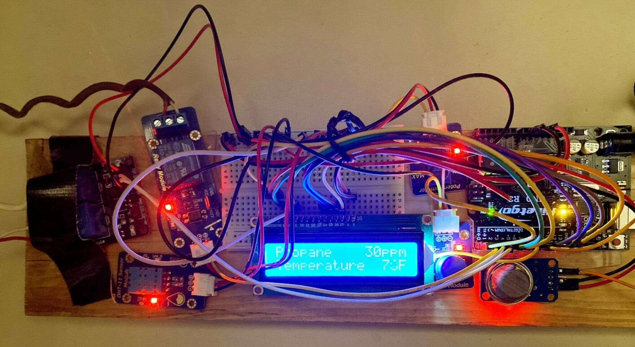
At the core of the design is an Arduino Uno connected to a DHT-11 temperature/humidity sensor, a MQ-2 gas sensor, and a few relays. I cover the basics of this design in the post on building an Arduino temperature sensor that communicates via USB. The core Arduino Uno thermostat could be built for under $100 by choosing only the necessary parts (but sensor kits are more fun, as they include sensors and parts that may be used on other projects):
If you're Arduino, most people start with the Uno or Nano models. If WiFi is desired, check out the ESP32 or ESP8266.
The following are affiliate links to other parts I used in this project. I never link to a product that I have not personally used.
| Preview | Product | |
|---|---|---|
![Arduino Uno REV3 [A000066]](https://m.media-amazon.com/images/I/51txW1iicVL._SL160_.jpg) | Arduino Uno REV3 [A000066] | |
 | Adeept Ultimate Sensor Kit for Raspberry Pi 4 3 Raspbian with C and Python Code | |
 | Battery Pack for Raspberry Pi, 4000mAh, Adhesive |
I’m also not the first person to build their own thermostat. I took inspiration from this smart Arduino thermostat, as well as this retro thermostat design. As you can see, I stuffed a few more parts into my design. The gas sensor in particular was meant to detect any propane leak or fire that might happen in the boiler room. I also stuck to the closed-loop principle from above, so that the core of the system requires nothing but power to protect the house.

While it may look complicated, it’s really just a bunch of simple examples stapled together. I also used the same easing functions from the temperature sensor project in order to smooth out the readings from the sensors.
I’m including the basic schematic and source code below, though this should not be treated as a “copy-and-paste” solution. Rather, it’s a starting point you might consider adapting into your own solution:
- Pin 7: DHT-11 data
- Pin 8: Rotary Button
- Pin 9: MQ-2
- Pins 5-6, 10-13: LCD Screen
/****************************************************************
  GLOBAL CONFIGURATION
****************************************************************/

#define NUM_ZONES    3
bool zone_states[NUM_ZONES];
char zone_names[NUM_ZONES][16] = { "Upstairs", "Bedroom", "Downstairs" };

#define NUM_SENSORS  7

#define LCD_COLS     16
#define LCD_ROWS     2

// Under this temperature, all modes are turned on:
#define SAFETY_TEMP  60

int lcdSensorsAt = 0;

#define SENSOR_UPDATE_MS 10000

/****************************************************************
  Sensors
****************************************************************/
#include "DHT.h"
#include <MQUnifiedsensor.h>
#include "EasingLib.h" // Smoothing algorithms.
#include <ArduinoJson.h>

StaticJsonDocument<256> sensor_json_doc;

class Sensor {
private:
  Easing _easing;
  float _value;

public:
  char name[16];
  char prefix[10];
  char unit[3];

  // Returns true if value changed.
  bool setValue(float value) {
    _easing.SetSetpoint(value);
    float ev = _easing.GetValue();
    if (abs(ev - _value) < 0.1) return false;
    _value = ev;
    sensor_json_doc[name] = ev;
    return true;
  }

  float getValue() {
    return _easing.GetValue();
  }

  Sensor(const char* sensor_name, const char* sensor_unit) {
    _easing = Easing();
    _value = 0.0;
    strcpy(name, sensor_name);
    strcpy(unit, sensor_unit);
  }
};

#define PIN_DHT11     7
#define PIN_MQ2       9

#define IMPERIAL true

Sensor sensors[NUM_SENSORS] = {
#if IMPERIAL
  Sensor("Temperature", "F"),
#else
  Sensor("Temperature", "C"),
#endif
  Sensor("Humidity", "%"),
  Sensor("H2", "ppm"),
  Sensor("LPG", "ppm"),
  Sensor("CO", "ppm"),
  Sensor("Alcohol", "ppm"),
  Sensor("Propane", "ppm")
};

DHT dht(PIN_DHT11, DHT11);
MQUnifiedsensor mq2(PIN_MQ2, 2);

// Returns true if any value changed.
bool updateSensors() {
  mq2.update();
  bool valueChanged = false;
  valueChanged = sensors[0].setValue(dht.readTemperature(IMPERIAL)) || valueChanged;
  valueChanged = sensors[1].setValue(dht.readHumidity()) || valueChanged;
  for (int x=2; x<NUM_SENSORS; x++) {
    valueChanged = sensors.setValue(mq2.readSensor(sensors.name)) || valueChanged;
  }
  return valueChanged;
}

bool areSensorsLoaded() {
  return sensors[NUM_SENSORS - 1].getValue() > 1;
}

/****************************************************************
  LCD
****************************************************************/
#include <LiquidCrystal.h>

// initialize the library with the numbers of the interface pins
LiquidCrystal lcd(5, 6, 10, 11, 12, 13);

void lcdPrintSensor(int sensorIdx) {
  sensorIdx = sensorIdx % NUM_SENSORS;
  char txt[LCD_COLS];
  char val[6];
  sprintf(val, "%d", (int)sensors[sensorIdx].getValue());
  lcd.print(sensors[sensorIdx].name);
  int numStartAt = LCD_COLS - strlen(val) - strlen(sensors[sensorIdx].unit);
  for (int x=strlen(sensors[sensorIdx].name); x<numStartAt; x++) {
    lcd.print(' ');
  }
  lcd.print(val);
  lcd.print(sensors[sensorIdx].unit);
}

void updateLcd() {
  lcd.setCursor(0, 0);
  if (!areSensorsLoaded()) {
    lcd.print("calibrating...");
    return;
  }
  lcdPrintSensor(lcdSensorsAt);
  lcd.setCursor(0, 1);
  lcdPrintSensor(lcdSensorsAt + 1);
}

/****************************************************************
  Input
****************************************************************/

#define PIN_BTN      8

int getButtonPressChange() {
  static bool isButtonPressed = false;
  bool pressState = digitalRead(PIN_BTN) == LOW;
  int ret = 0;
  if (pressState != isButtonPressed) {
    if (pressState) ret = 1;
    else ret = -1;
  }
  isButtonPressed = pressState;
  return ret;
}

bool updateInput() {
  if (getButtonPressChange() != 1) return false;

  lcdSensorsAt += 1;
  if (lcdSensorsAt < 0) lcdSensorsAt = NUM_SENSORS - 1;
  else if (lcdSensorsAt >= NUM_SENSORS) lcdSensorsAt = 0;
  lcd.display();
  return true;
}

/****************************************************************
  HVAC
****************************************************************/

bool isSafetyModeEngaged() {
  return sensors[0].getValue() <= SAFETY_TEMP;
}

void setHeating(int zone, bool heatOn) {
  bool safety = isSafetyModeEngaged();
  int pin = zone + 2;
  char* zone_name = zone_names[zone];

  bool realHeatOn = heatOn || safety;
  if (sensor_json_doc[zone_name].as<bool>() == realHeatOn)
    return;
  pinMode(pin, realHeatOn ? HIGH : LOW);
  digitalWrite(LED_BUILTIN, safety ? HIGH : LOW);
  sensor_json_doc[zone_name] = realHeatOn;
  zone_states[zone] = heatOn;
}

// {"bedroom":true}
bool readSerialCommand() {
  while (Serial.available() && Serial.peek() != '{')
    Serial.read(); // Wait for JSON-start.
  if (!Serial.available()) return false;
  StaticJsonDocument<128> doc;
  auto error = deserializeJson(doc, Serial);
  if (error) {
    Serial.println(error.c_str());
    // Chomp past the entire string (reset).
    while (Serial.available()) Serial.read();
    return false;
  }
  JsonObject root = doc.as<JsonObject>(); // get the root object

  for (JsonObject::iterator it=root.begin(); it!=root.end(); ++it) {
    const char* key = it->key().c_str();
    int zone = -1;
    for (int x=0; x<NUM_ZONES; x++) {
      if (strcasecmp(zone_names, key) == 0) {
        zone = x;
        break;
      }
    }
    if (zone < 0) {
      sscanf(key, "%d", &zone);
    }
    if (zone < 0 || zone >= NUM_ZONES) {
      Serial.println("Invalid Heater");
      continue;
    }
    bool val = it->value().as<bool>();
    setHeating(zone, val);
    serializeJson(sensor_json_doc, Serial);
    Serial.println("");
  }
  return true;
}

/****************************************************************
  Main
****************************************************************/

void setup() {
  Serial.begin(9600);
  Serial.setTimeout(1000);

  dht.begin();
  pinMode(PIN_BTN, INPUT);
  pinMode(PIN_MQ2, INPUT);
  pinMode(PIN_DHT11, INPUT);

  lcd.begin(LCD_COLS, LCD_ROWS);
  lcd.clear();
  updateSensors();
  for (int x=0; x<NUM_ZONES; x++) {
    pinMode(x + 2, OUTPUT);
    zone_states = false;
    sensor_json_doc[zone_names] = false;
    pinMode(x + 2, LOW);
  }
  updateLcd();
}


void loop() {
  static unsigned long lastSensorUpdate;
  unsigned long now = millis();
  unsigned long elapsed = now - lastSensorUpdate;
  bool updatingSensors = elapsed >= SENSOR_UPDATE_MS;

  bool displayChanged = readSerialCommand ();
  displayChanged = updateInput() || displayChanged;
  if (updatingSensors) {
    displayChanged = updateSensors() || displayChanged;
    // Give everything some time to start up and collect initial readings.
    if (areSensorsLoaded()) {
      for (int x=0; x<NUM_ZONES; x++) {
        // Trigger an update for safety mode, if needed.
        setHeating(x, zone_states);
      }
      serializeJson(sensor_json_doc, Serial);
      Serial.println("");
      displayChanged = true;
    }
  }
  if (displayChanged) updateLcd();
  if (updatingSensors) lastSensorUpdate = now;
}
This code outputs data as JSON to the USB port, just like the other sensor project. The relevant configuration block is:
Sensor sensors[NUM_SENSORS] = {
#if IMPERIAL
  Sensor("Temperature", "F"),
#else
  Sensor("Temperature", "C"),
#endif
  Sensor("Humidity", "%"),
  Sensor("H2", "ppm"),
  Sensor("LPG", "ppm"),
  Sensor("CO", "ppm"),
  Sensor("Alcohol", "ppm"),
  Sensor("Propane", "ppm")
};
The data is written via USB every 10 seconds (SENSOR_UPDATE_MS). It also can be controlled via the serial port, setting the on/off state manually. For example, the JSON payload {"bedroom": true}, written via the USB port, will turn on the Bedroom zone.
With the basic code in place, I began to test the reliability…
Reliability Tests
I brought my laptop over to the boiler room and left it connected to the Arduino Uno, so that I could use the Arduino IDE in order to manually test the zones via the Serial Debugger. I ran standard resiliency tests, like cutting out the power and then reconnecting the Arduino Uno randomly.

I watched the relays turn on and off and could hear the hot water flowing to each zone. Just to be sure everything was reliable, I continued to test manually in this way for a couple days.
At first, everything seemed fine. Slowly I began to notice that one of the rooms was never getting cold, though. I took a look at the motor for the zone (right) and noticed that it was stuck on, even when the relay indicated it should have been off. I soon discovered that the gear mechanism itself was stuck. Even after cleaning and oiling it, it proved unreliable, often failing to turn on the zone. In the end, I ended up buying a replacement motor for $25. Since then, each zone has turned on and off flawlessly.
DIY Programmable Thermostat
To make the thermostat smart, two more things were required:
- Temperature readings from each zone.
- A programmable controller.
For temperature readings, I used a combination of other sensors fed into Home Assistant. For example, the downstairs temperature is taken as an average of two sensors in different rooms using the following yaml configuration in Home Assistant:
sensor:
  - platform: template
    sensors:
      downstairs_temperature:
        friendly_name: "Downstairs"
        unit_of_measurement: "°F"
        device_class: temperature
        value_template: >-
          {% set ts = [
            states('sensor.office_temperature') | float,
            states('sensor.family_room_temperature') | float
          ] | select("greaterthan", 10) | list %}
          {{ ts | sum / ts | count }}
I attached the USB directly to a Raspberry Pi running Node RED, feeding the JSON output from the sensor into Home Assistant via the community add-on (here are some code samples). To handle the scheduling, I found the ramp-thermostat add-on:
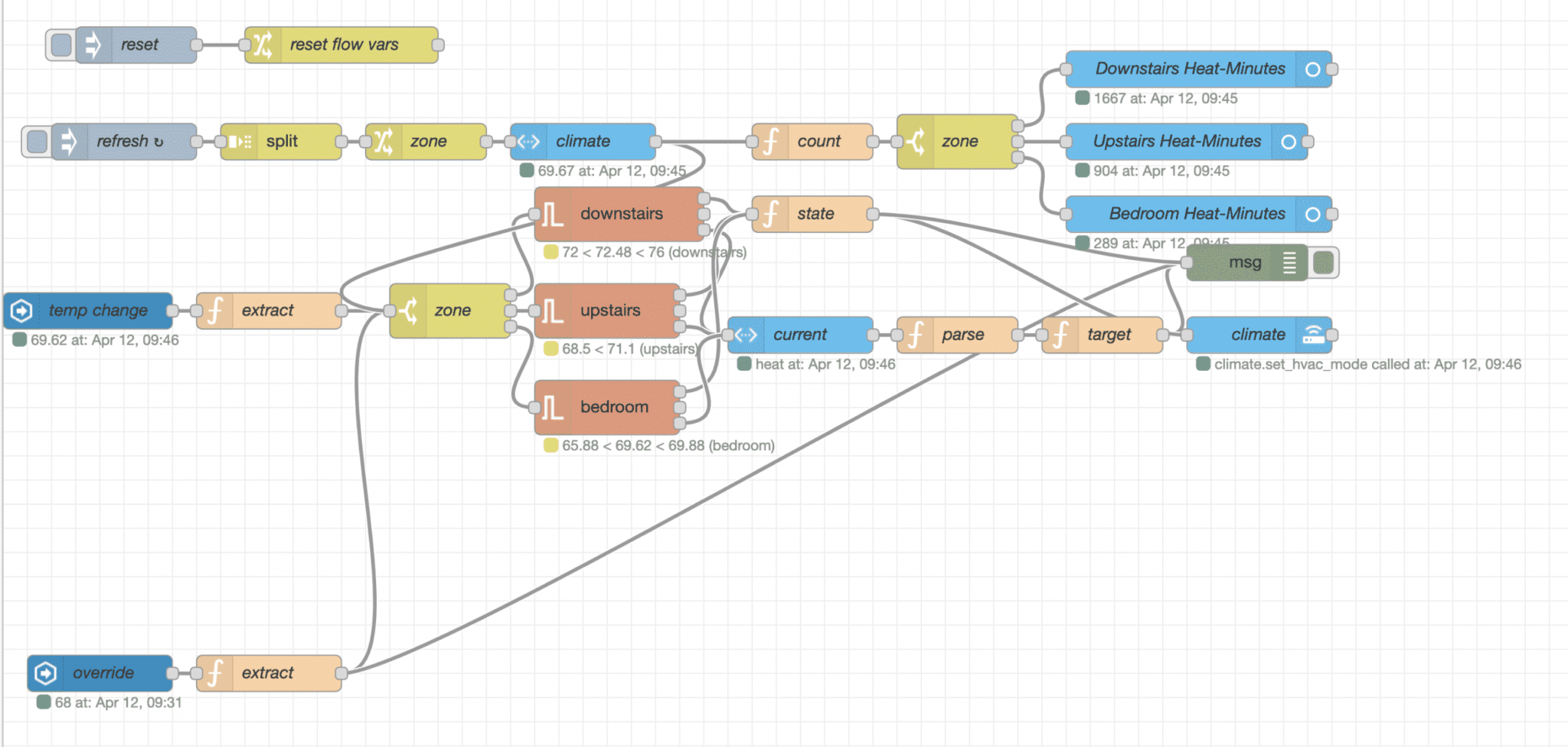
If it looks complicated, that’s because I added some bells and whistles to the Raspberry Pi thermostat. There are some extra sensor variables being exported to Home Assistant, for better monitoring (below). There’s also an “override” feature, so that changes made to the target temperature on the Home Assistant side (e.g., though the Lovelace UI) temporarily take priority over the pre-programmed schedule.
Here’s the full Node RED JSON flow and home assistant package (packages/themostat.yaml). Again, these should be treated as code samples for adaptation rather than copy-and-paste solutions (your HVAC system is certainly different than mine). That said, the code is made to be reusable. If you have any troubles, I’m happy to help in the comments below (or contact me directly).
[
  {
    "id": "3b595b03.f81df4",
    "type": "tab",
    "label": "Scheduler",
    "disabled": false,
    "info": ""
  },
  {
    "id": "4985c2aa.a29a9c",
    "type": "debug",
    "z": "3b595b03.f81df4",
    "name": "",
    "active": true,
    "tosidebar": true,
    "console": false,
    "tostatus": false,
    "complete": "true",
    "targetType": "full",
    "x": 1030,
    "y": 240,
    "wires": []
  },
  {
    "id": "2f05f176.e923de",
    "type": "ramp-thermostat",
    "z": "3b595b03.f81df4",
    "name": "downstairs",
    "profile": "9de68e17.56ef",
    "hysteresisplus": "2",
    "hysteresisminus": "2",
    "x": 510,
    "y": 200,
    "wires": [
      [
        "c84e280.985ddd8"
      ],
      [],
      [
        "e43af114.d891d"
      ]
    ]
  },
  {
    "id": "d1309f6f.900f5",
    "type": "server-state-changed",
    "z": "3b595b03.f81df4",
    "name": "temp change",
    "server": "fa9e2f15.e1b39",
    "version": 1,
    "exposeToHomeAssistant": false,
    "haConfig": [
      {
        "property": "name",
        "value": ""
      },
      {
        "property": "icon",
        "value": ""
      }
    ],
    "entityidfilter": "^sensor.(downstairs|upstairs|bedroom)_temperature$",
    "entityidfiltertype": "regex",
    "outputinitially": true,
    "state_type": "num",
    "haltifstate": "",
    "halt_if_type": "str",
    "halt_if_compare": "is",
    "outputs": 1,
    "output_only_on_state_change": true,
    "x": 70,
    "y": 280,
    "wires": [
      [
        "48c840ed.5cc16"
      ]
    ]
  },
  {
    "id": "efaa0423.4e8018",
    "type": "api-call-service",
    "z": "3b595b03.f81df4",
    "name": "climate",
    "server": "fa9e2f15.e1b39",
    "version": 1,
    "debugenabled": false,
    "service_domain": "climate",
    "service": "",
    "entityId": "",
    "data": "",
    "dataType": "json",
    "mergecontext": "",
    "output_location": "",
    "output_location_type": "none",
    "mustacheAltTags": false,
    "x": 1040,
    "y": 300,
    "wires": [
      []
    ]
  },
  {
    "id": "48c840ed.5cc16",
    "type": "function",
    "z": "3b595b03.f81df4",
    "name": "extract",
    "func": "msg.zone = msg.topic.substr('sensor.'.length).split('_')[0]\nmsg.topic = 'setCurrent'\nreturn msg;",
    "outputs": 1,
    "noerr": 0,
    "x": 220,
    "y": 280,
    "wires": [
      [
        "6ad1159b.fb34cc"
      ]
    ]
  },
  {
    "id": "6ad1159b.fb34cc",
    "type": "switch",
    "z": "3b595b03.f81df4",
    "name": "zone",
    "property": "zone",
    "propertyType": "msg",
    "rules": [
      {
        "t": "eq",
        "v": "downstairs",
        "vt": "str"
      },
      {
        "t": "eq",
        "v": "upstairs",
        "vt": "str"
      },
      {
        "t": "eq",
        "v": "bedroom",
        "vt": "str"
      }
    ],
    "checkall": "true",
    "repair": false,
    "outputs": 3,
    "x": 370,
    "y": 280,
    "wires": [
      [
        "2f05f176.e923de"
      ],
      [
        "6131f886.f047c8"
      ],
      [
        "50cd14b7.0b2b6c"
      ]
    ]
  },
  {
    "id": "6131f886.f047c8",
    "type": "ramp-thermostat",
    "z": "3b595b03.f81df4",
    "name": "upstairs",
    "profile": "f9de753d.53f0f8",
    "hysteresisplus": "2",
    "hysteresisminus": "2",
    "x": 500,
    "y": 280,
    "wires": [
      [
        "c84e280.985ddd8"
      ],
      [],
      [
        "e43af114.d891d"
      ]
    ]
  },
  {
    "id": "50cd14b7.0b2b6c",
    "type": "ramp-thermostat",
    "z": "3b595b03.f81df4",
    "name": "bedroom",
    "profile": "fc2037fe.c4b858",
    "hysteresisplus": "2",
    "hysteresisminus": "2",
    "x": 500,
    "y": 360,
    "wires": [
      [
        "c84e280.985ddd8"
      ],
      [],
      [
        "e43af114.d891d"
      ]
    ]
  },
  {
    "id": "da5a079.a5039f8",
    "type": "function",
    "z": "3b595b03.f81df4",
    "name": "target",
    "func": "oldTemp = msg.climate.attributes.temperature\nif (Math.abs(msg.temp - oldTemp) < Number.EPSILON) {\n    // Do not change temperatures if the target is the same.\n    // This (1) prevents spam (2) allows manual-override.\n    return null;\n}\nmsg.payload = {}\nmsg.payload.service = 'set_temperature'\nmsg.payload.data = {}\nmsg.payload.data.entity_id = 'climate.' + msg.zone\nmsg.payload.data.temperature = msg.temp\n\nmsg.zd.temperature = msg.temp\nmsg.zd.current_temp = msg.current_temp\nflow.set(msg.zone, msg.zd);\n\nreturn msg;",
    "outputs": 1,
    "noerr": 0,
    "x": 910,
    "y": 300,
    "wires": [
      [
        "4985c2aa.a29a9c",
        "efaa0423.4e8018"
      ]
    ]
  },
  {
    "id": "88826b55.1882e8",
    "type": "inject",
    "z": "3b595b03.f81df4",
    "name": "reset",
    "topic": "",
    "payload": "",
    "payloadType": "date",
    "repeat": "",
    "crontab": "",
    "once": false,
    "onceDelay": 0.1,
    "x": 110,
    "y": 60,
    "wires": [
      [
        "3cc67737.296838"
      ]
    ]
  },
  {
    "id": "3cc67737.296838",
    "type": "change",
    "z": "3b595b03.f81df4",
    "name": "reset flow vars",
    "rules": [
      {
        "t": "delete",
        "p": "downstairs",
        "pt": "flow"
      },
      {
        "t": "delete",
        "p": "upstairs",
        "pt": "flow"
      },
      {
        "t": "delete",
        "p": "bedroom",
        "pt": "msg"
      }
    ],
    "action": "",
    "property": "",
    "from": "",
    "to": "",
    "reg": false,
    "x": 280,
    "y": 60,
    "wires": [
      []
    ]
  },
  {
    "id": "e00c4ea8.b0057",
    "type": "server-state-changed",
    "z": "3b595b03.f81df4",
    "name": "override",
    "server": "fa9e2f15.e1b39",
    "version": 1,
    "exposeToHomeAssistant": false,
    "haConfig": [
      {
        "property": "name",
        "value": ""
      },
      {
        "property": "icon",
        "value": ""
      }
    ],
    "entityidfilter": "^sensor.(downstairs|upstairs|bedroom)_target_temperature$",
    "entityidfiltertype": "regex",
    "outputinitially": false,
    "state_type": "num",
    "haltifstate": "",
    "halt_if_type": "str",
    "halt_if_compare": "is",
    "outputs": 1,
    "output_only_on_state_change": true,
    "x": 80,
    "y": 580,
    "wires": [
      [
        "70e37158.e169c"
      ]
    ]
  },
  {
    "id": "70e37158.e169c",
    "type": "function",
    "z": "3b595b03.f81df4",
    "name": "extract",
    "func": "msg.zone = msg.topic.substr('sensor.'.length).split('_')[0]\nmsg.topic = 'setTarget'\n\nmsg.zd = flow.get(msg.zone) || {};\nif (msg.zd.temperature && Math.abs(msg.zd.temperature - msg.payload) < 1) {\n    // Do not \"setTarget\" if the temperature was changed by us.\n    return null;\n}\n\nreturn msg;",
    "outputs": 1,
    "noerr": 0,
    "x": 220,
    "y": 580,
    "wires": [
      [
        "6ad1159b.fb34cc",
        "4985c2aa.a29a9c"
      ]
    ]
  },
  {
    "id": "1e87d11d.b2c52f",
    "type": "function",
    "z": "3b595b03.f81df4",
    "name": "parse",
    "func": "msg.current_state = msg.climate.state == 'heat'\nmsg.current_temp = msg.climate.attributes.current_temperature\nmsg.temp = msg.payload\n/*if (msg.override.state > msg.override.attributes.min) {\n  msg.temp = msg.override.state;\n}*/\n\nmsg.zd = flow.get(msg.zone) || {};\nmsg.temp = Math.round(msg.temp);\n\nreturn msg;",
    "outputs": 1,
    "noerr": 0,
    "x": 790,
    "y": 300,
    "wires": [
      [
        "da5a079.a5039f8"
      ]
    ]
  },
  {
    "id": "e43af114.d891d",
    "type": "api-current-state",
    "z": "3b595b03.f81df4",
    "name": "current",
    "server": "fa9e2f15.e1b39",
    "version": 1,
    "outputs": 1,
    "halt_if": "",
    "halt_if_type": "str",
    "halt_if_compare": "is",
    "override_topic": false,
    "entity_id": "climate.{{zone}}",
    "state_type": "str",
    "state_location": "climate_state",
    "override_payload": "msg",
    "entity_location": "climate",
    "override_data": "msg",
    "blockInputOverrides": false,
    "x": 660,
    "y": 300,
    "wires": [
      [
        "1e87d11d.b2c52f"
      ]
    ]
  },
  {
    "id": "d483d85c.a88688",
    "type": "inject",
    "z": "3b595b03.f81df4",
    "name": "refresh",
    "topic": "",
    "payload": "upstairs downstairs bedroom",
    "payloadType": "str",
    "repeat": "60",
    "crontab": "",
    "once": false,
    "onceDelay": 0.1,
    "x": 100,
    "y": 140,
    "wires": [
      [
        "a1c4a123.595b6"
      ]
    ]
  },
  {
    "id": "a1c4a123.595b6",
    "type": "split",
    "z": "3b595b03.f81df4",
    "name": "",
    "splt": " ",
    "spltType": "str",
    "arraySplt": 1,
    "arraySpltType": "len",
    "stream": false,
    "addname": "",
    "x": 230,
    "y": 140,
    "wires": [
      [
        "af05bfb4.d6f2c"
      ]
    ]
  },
  {
    "id": "af05bfb4.d6f2c",
    "type": "change",
    "z": "3b595b03.f81df4",
    "name": "zone",
    "rules": [
      {
        "t": "set",
        "p": "zone",
        "pt": "msg",
        "to": "payload",
        "tot": "msg"
      }
    ],
    "action": "",
    "property": "",
    "from": "",
    "to": "",
    "reg": false,
    "x": 350,
    "y": 140,
    "wires": [
      [
        "9c533525.8806b8"
      ]
    ]
  },
  {
    "id": "9c533525.8806b8",
    "type": "api-current-state",
    "z": "3b595b03.f81df4",
    "name": "climate",
    "server": "fa9e2f15.e1b39",
    "version": 1,
    "outputs": 1,
    "halt_if": "",
    "halt_if_type": "str",
    "halt_if_compare": "is",
    "override_topic": false,
    "entity_id": "sensor.{{zone}}_temperature",
    "state_type": "str",
    "state_location": "payload",
    "override_payload": "msg",
    "entity_location": "",
    "override_data": "none",
    "blockInputOverrides": false,
    "x": 480,
    "y": 140,
    "wires": [
      [
        "6ad1159b.fb34cc",
        "6f2b494f.d46338"
      ]
    ]
  },
  {
    "id": "c84e280.985ddd8",
    "type": "function",
    "z": "3b595b03.f81df4",
    "name": "state",
    "func": "state = msg.payload\n\nmsg.payload = {}\nmsg.payload.service = 'set_hvac_mode'\nmsg.payload.data = {}\nmsg.payload.data.entity_id = 'climate.' + msg.zone\nmsg.payload.data.hvac_mode = state ? 'heat' : 'off';\n\nmsg.zd = flow.get(msg.zone) || {};\nmsg.zd.state = state;\nflow.set(msg.zone, msg.zd)\n\nreturn msg;",
    "outputs": 1,
    "noerr": 0,
    "x": 670,
    "y": 200,
    "wires": [
      [
        "efaa0423.4e8018",
        "4985c2aa.a29a9c"
      ]
    ]
  },
  {
    "id": "6f2b494f.d46338",
    "type": "function",
    "z": "3b595b03.f81df4",
    "name": "count",
    "func": "msg.zd = flow.get(msg.zone) || {};\nif (!msg.zd.state) {\n    // Not on. Nothing to do.\n    return null;\n}\nhm = (msg.zd.heat_min || 0) + 1;\n// The heater is on. Increment by one heat-minute.\nmsg.payload = hm\nmsg.zd.heat_min = hm;\nflow.set(msg.zone, msg.zd);\nreturn msg;",
    "outputs": 1,
    "noerr": 0,
    "x": 670,
    "y": 140,
    "wires": [
      [
        "f7ab9a58.47c8f8"
      ]
    ]
  },
  {
    "id": "b49f04aa.3b94e8",
    "type": "ha-entity",
    "z": "3b595b03.f81df4",
    "name": "Downstairs Heat-Minutes",
    "server": "fa9e2f15.e1b39",
    "version": 1,
    "debugenabled": false,
    "outputs": 1,
    "entityType": "sensor",
    "config": [
      {
        "property": "name",
        "value": "downstairs_heat_min"
      },
      {
        "property": "device_class",
        "value": ""
      },
      {
        "property": "icon",
        "value": ""
      },
      {
        "property": "unit_of_measurement",
        "value": "min"
      }
    ],
    "state": "payload",
    "stateType": "msg",
    "attributes": [],
    "resend": true,
    "outputLocation": "",
    "outputLocationType": "none",
    "inputOverride": "allow",
    "x": 990,
    "y": 80,
    "wires": [
      []
    ]
  },
  {
    "id": "f7ab9a58.47c8f8",
    "type": "switch",
    "z": "3b595b03.f81df4",
    "name": "zone",
    "property": "zone",
    "propertyType": "msg",
    "rules": [
      {
        "t": "eq",
        "v": "downstairs",
        "vt": "str"
      },
      {
        "t": "eq",
        "v": "upstairs",
        "vt": "str"
      },
      {
        "t": "eq",
        "v": "bedroom",
        "vt": "str"
      }
    ],
    "checkall": "true",
    "repair": false,
    "outputs": 3,
    "x": 790,
    "y": 140,
    "wires": [
      [
        "b49f04aa.3b94e8"
      ],
      [
        "5962ba35.52a804"
      ],
      [
        "d906d8ef.c65908"
      ]
    ]
  },
  {
    "id": "5962ba35.52a804",
    "type": "ha-entity",
    "z": "3b595b03.f81df4",
    "name": "Upstairs Heat-Minutes",
    "server": "fa9e2f15.e1b39",
    "version": 1,
    "debugenabled": false,
    "outputs": 1,
    "entityType": "sensor",
    "config": [
      {
        "property": "name",
        "value": "upstairs_heat_min"
      },
      {
        "property": "device_class",
        "value": ""
      },
      {
        "property": "icon",
        "value": ""
      },
      {
        "property": "unit_of_measurement",
        "value": "min"
      }
    ],
    "state": "payload",
    "stateType": "msg",
    "attributes": [],
    "resend": true,
    "outputLocation": "",
    "outputLocationType": "none",
    "inputOverride": "allow",
    "x": 980,
    "y": 140,
    "wires": [
      []
    ]
  },
  {
    "id": "d906d8ef.c65908",
    "type": "ha-entity",
    "z": "3b595b03.f81df4",
    "name": "Bedroom Heat-Minutes",
    "server": "fa9e2f15.e1b39",
    "version": 1,
    "debugenabled": false,
    "outputs": 1,
    "entityType": "sensor",
    "config": [
      {
        "property": "name",
        "value": "bedroom_heat_min"
      },
      {
        "property": "device_class",
        "value": ""
      },
      {
        "property": "icon",
        "value": ""
      },
      {
        "property": "unit_of_measurement",
        "value": "min"
      }
    ],
    "state": "payload",
    "stateType": "msg",
    "attributes": [],
    "resend": true,
    "outputLocation": "",
    "outputLocationType": "none",
    "inputOverride": "allow",
    "x": 990,
    "y": 200,
    "wires": [
      []
    ]
  },
  {
    "id": "9de68e17.56ef",
    "type": "profile",
    "z": "",
    "name": "downstairs",
    "time1": "00:00",
    "temp1": "60",
    "time2": "06:00",
    "temp2": "74",
    "time3": "16:00",
    "temp3": "74",
    "time4": "22:00",
    "temp4": "60",
    "time5": "23:59",
    "temp5": "60",
    "time6": "",
    "temp6": "",
    "time7": "",
    "temp7": "",
    "time8": "",
    "temp8": "",
    "time9": "",
    "temp9": "",
    "time10": "",
    "temp10": ""
  },
  {
    "id": "fa9e2f15.e1b39",
    "type": "server",
    "z": "",
    "name": "Cabin",
    "legacy": false,
    "addon": false,
    "rejectUnauthorizedCerts": true,
    "ha_boolean": "y|yes|true|on|home|open",
    "connectionDelay": true,
    "cacheJson": true
  },
  {
    "id": "f9de753d.53f0f8",
    "type": "profile",
    "z": "",
    "name": "upstairs",
    "time1": "00:00",
    "temp1": "62",
    "time2": "05:00",
    "temp2": "72",
    "time3": "18:00",
    "temp3": "75",
    "time4": "22:00",
    "temp4": "75",
    "time5": "23:59",
    "temp5": "62",
    "time6": "",
    "temp6": "",
    "time7": "",
    "temp7": "",
    "time8": "",
    "temp8": "",
    "time9": "",
    "temp9": "",
    "time10": "",
    "temp10": ""
  },
  {
    "id": "fc2037fe.c4b858",
    "type": "profile",
    "z": "",
    "name": "bedroom",
    "time1": "00:00",
    "temp1": "65",
    "time2": "05:00",
    "temp2": "65",
    "time3": "08:00",
    "temp3": "72",
    "time4": "11:00",
    "temp4": "65",
    "time5": "23:59",
    "temp5": "65",
    "time6": "",
    "temp6": "",
    "time7": "",
    "temp7": "",
    "time8": "",
    "temp8": "",
    "time9": "",
    "temp9": "",
    "time10": "",
    "temp10": ""
  }
]
sensor:
- platform: template
sensors:
downstairs_temperature:
friendly_name: "Downstairs"
unit_of_measurement: "°F"
device_class: temperature
value_template: >-
{% set ts = [
states('sensor.office_temperature') | float,
states('sensor.family_room_temperature') | float
] | select("greaterthan", 10) | list %}
{{ ts | sum / ts | count }}
downstairs_target_temperature:
friendly_name: "Downstairs HVAC Target"
unit_of_measurement: "°F"
device_class: temperature
value_template: "{{ states.climate.downstairs.attributes.temperature }}"
downstairs_humidity:
friendly_name: "Downstairs Humidity"
unit_of_measurement: "%"
device_class: humidity
value_template: "{{ states('sensor.office_humidity') }}"
upstairs_temperature:
friendly_name: "Upstairs"
unit_of_measurement: "°F"
device_class: temperature
# Average temperature of sensors in room:
value_template: >-
{% set ts = [
states('sensor.great_room_temperature') | float,
states('sensor.stairwell_temperature') | float
] | select("greaterthan", 10) | list %}
{{ ts | sum / ts | count }}
upstairs_humidity:
friendly_name: "Upstairs Humidity"
unit_of_measurement: "%"
device_class: humidity
value_template: "{{ states('sensor.great_room_humidity') }}"
upstairs_target_temperature:
friendly_name: "Upstairs HVAC Target"
unit_of_measurement: "°F"
device_class: temperature
value_template: "{{ states.climate.upstairs.attributes.temperature }}"
bedroom_temperature:
friendly_name: "Bedroom"
unit_of_measurement: "°F"
device_class: temperature
value_template: "{{ states('sensor.bedroom_window_temperature') }}"
bedroom_target_temperature:
friendly_name: "Bedroom HVAC Target"
unit_of_measurement: "°F"
device_class: temperature
value_template: "{{ states.climate.bedroom.attributes.temperature }}"
bedroom_humidity:
friendly_name: "Bedroom Humidity"
unit_of_measurement: "%"
device_class: humidity
value_template: "{{ states('sensor.bedroom_window_humidity') }}"
climate:
- platform: generic_thermostat
name: Downstairs
initial_hvac_mode: "heat"
heater: switch.radiators_downstairs
target_sensor: sensor.downstairs_temperature
target_temp: 60
away_temp: 50
min_temp: 40
- platform: generic_thermostat
name: Upstairs
initial_hvac_mode: "heat"
heater: switch.radiators_upstairs
target_sensor: sensor.upstairs_temperature
target_temp: 60
away_temp: 50
min_temp: 40
- platform: generic_thermostat
name: Bedroom
initial_hvac_mode: "heat"
heater: switch.radiators_bedroom
target_sensor: sensor.bedroom_temperature
target_temp: 60
away_temp: 50
min_temp: 40
I then use the Simple Thermostat card to show each of the three zones in the Home Assistant UI:

Monitoring & Optimizing
Home Assistant does have built-in history for climate controls. However, I thought I might do a little better with Grafana and Prometheus. Using the design shown there, we can track the HVAC performance over time. Some zones struggled to keep up with the heating demands:

To improve this, we began adding electric heaters to those rooms which required it. This gave us an opportunity to offset the cost of propane with (much cheaper) electricity. The same Home Assistant switches that controlled the radiators, above, were reconfigured to also turn on the electric heaters for that zone.
It took some fiddling to get the temperature readings right, as well. Eventually we ended up with two sensors in each zone. The DHT-11 attached to the central thermostat itself is only accurate enough for a fallback sensor. Elsewhere, I used the SHT31-D sensor — which is much more accurate and precise.
Adding Accuracy
To really dial-in the HVAC system, more sensors are required.
The additional SHT31-D sensors run about $15 each, with ESP8266s costing about $4 each… so each additional temperature+humidity reading costs about $20 total. The following post breaks down the process:


In many cases, cheap ambient air temperature sensors are fine. However, it's possible to save a good deal of money on electricity and gas through the use of more accurate sensors. This post breaks down the cheapest, most accurate temperature sensor build I've found so far.


